Though each company has its own drafting standards, the practises set forth in this post may not be exactly the same practises followed in all corporations.
The practises given are in general agreement with recommendations set forth in ANSI standards.
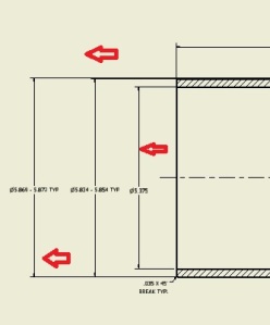
- Place dimensions outside the view. Unless they will be more easily and quickly understood.
2.Place dimensions between views unless the rules such as the contour rule, the rule against crowding and so forth, prevent their being so placed
3. If possible avoid crossing two dimension lines
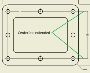
4. A centre line may be extended to serve as an extension line
5. Keep parallel dimension equally spaced
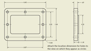
6. Always give locating dimensions to the centres of circles that represent holes, cylindrical projections or bosses.
7. If possible attach the location dimension for holes to the view on which they appear as circles.
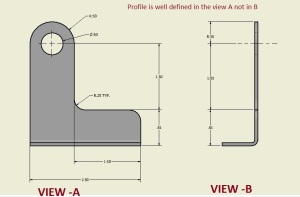
8. Group related dimensions on the view showing the contour of a feature
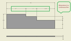
9. Arrange a series of dimensions in a continuous line.
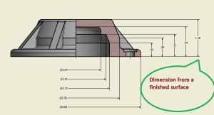
10. Dimension from a finished surface, centreline or baseline that can be readily established
11. Stagger the figures in a series of parallel dimension lines to allow sufficient space for the figures and to prevent confusion
Refer above Figure
12. Do not repeat dimensions
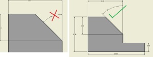
13. When an arc is used as a dimension line for an angular measurement use the vertex of the angle as the centre. It is usually undesirable to terminate the dimension line for an angle at lines that represent surfaces.it is better practise to use an extension line.
14. Place the figures of angular dimensions so they will read from the bottom of a drawing except in the case of large angles.


 0
0